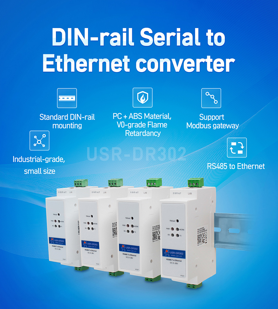
Basic Function of Din Rail RS485 to Ethernet Converter USR-DR302
Realize bidirectional transparent transmission
between RS485 and Ethernet

DIN-rail mounted RS485 to Ethernet Converter
Small size, easy to manage and maintain, cost-effective
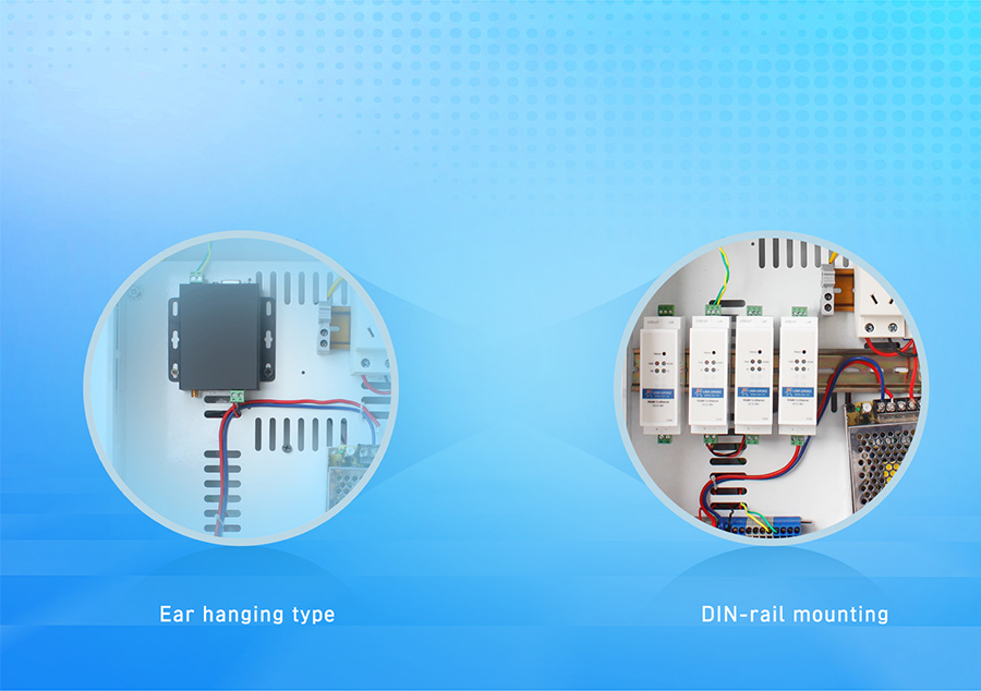
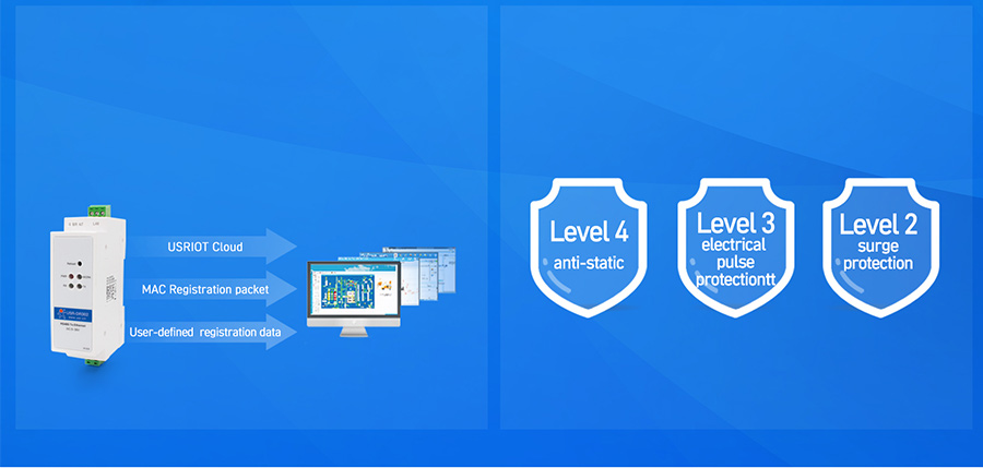
Function Diagram

Working Mode
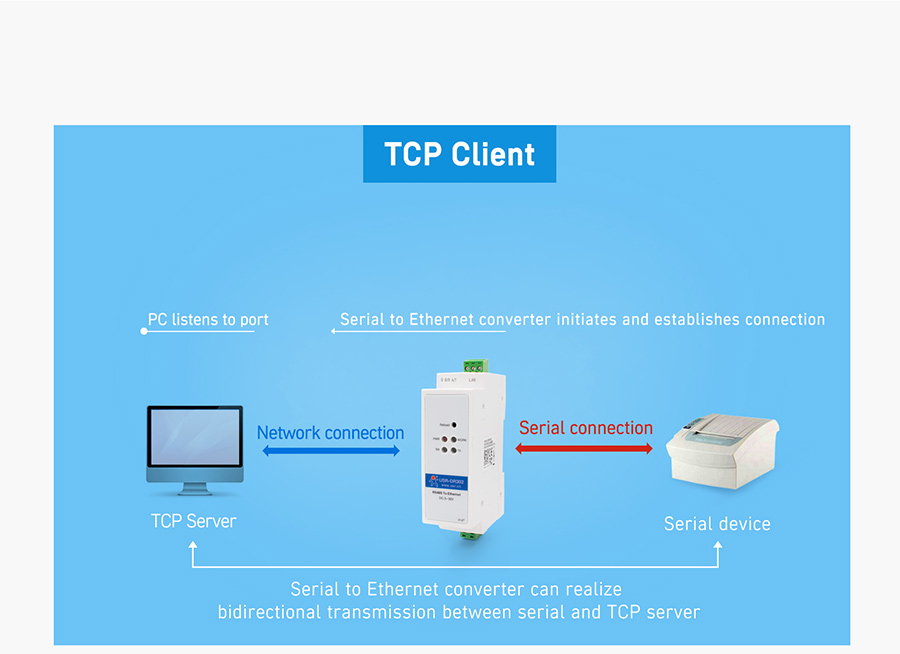
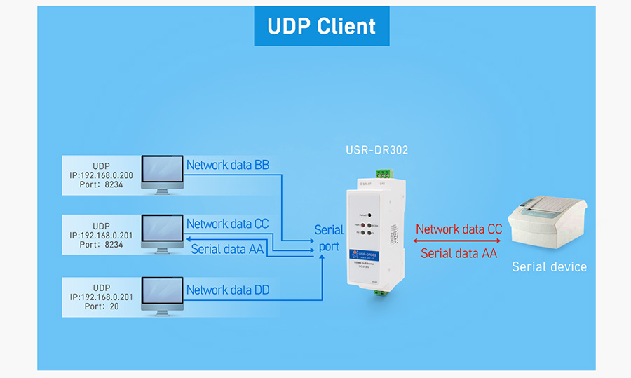
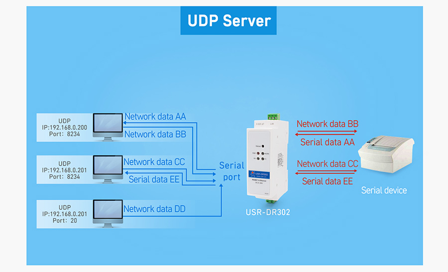
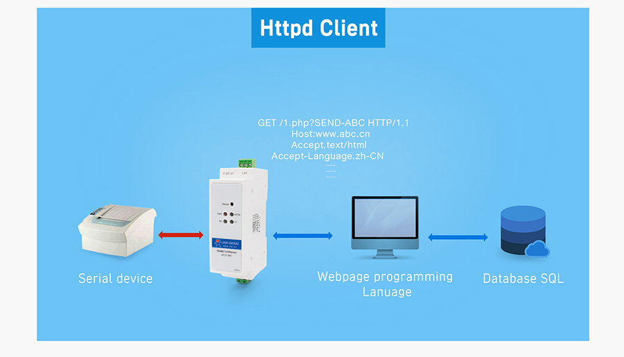
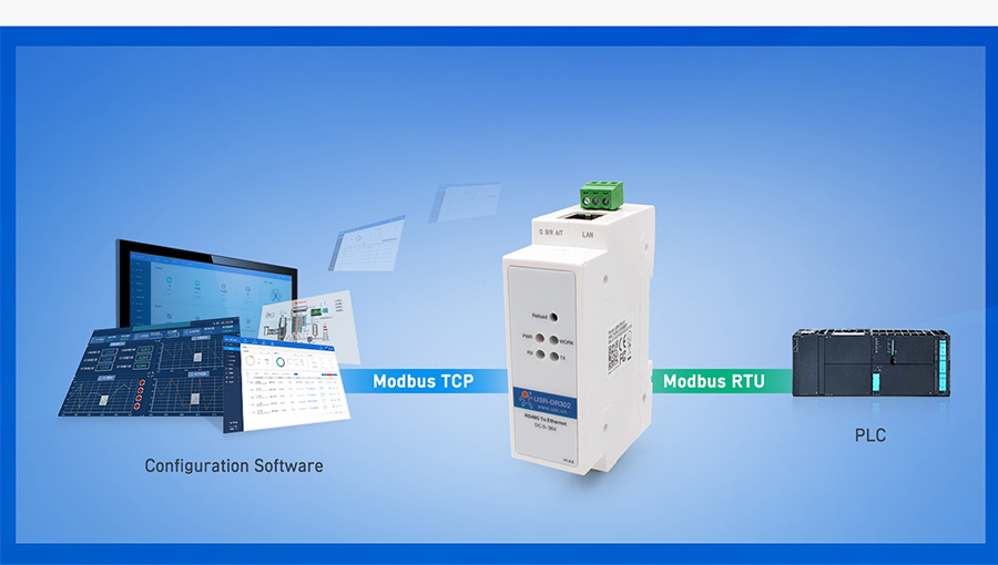
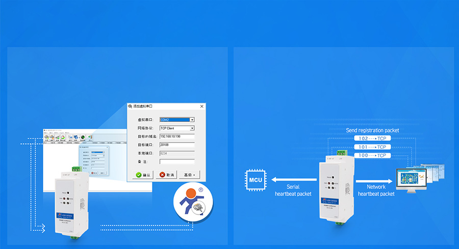

Power data networking transmission
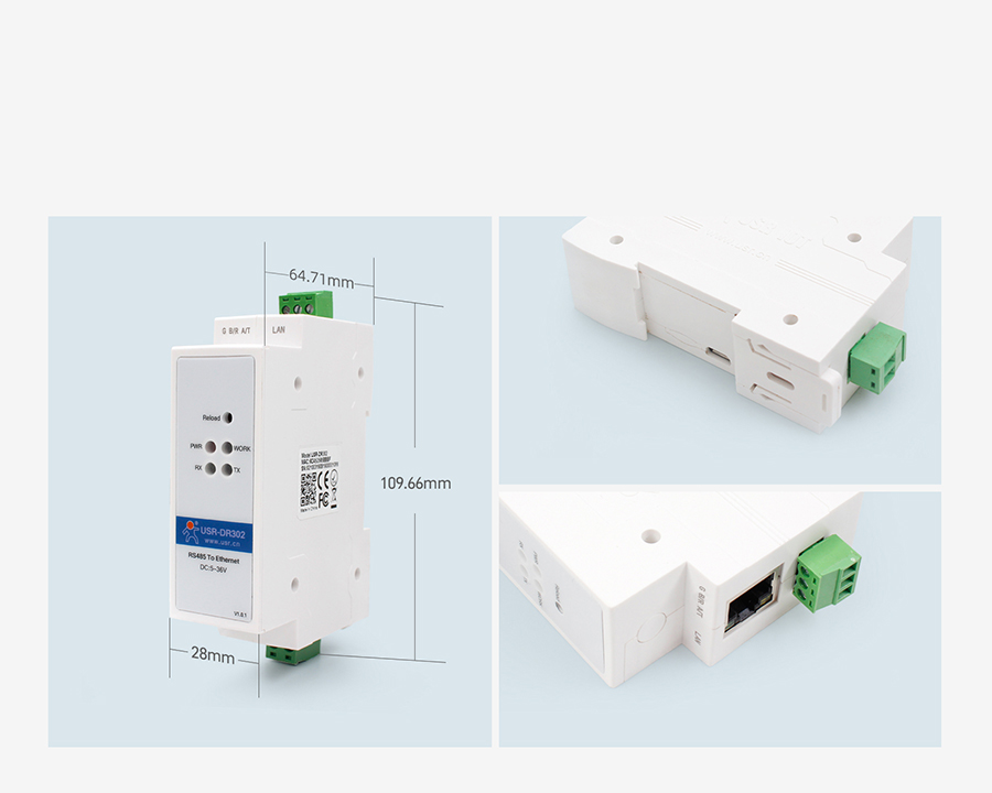
Small size which is available for narrow space;
DIN-rail mounting, easy to install on the wall;
The terminal data of the distribution box can quickly convert into the network data,
real-time communication, reduce the cost effectively
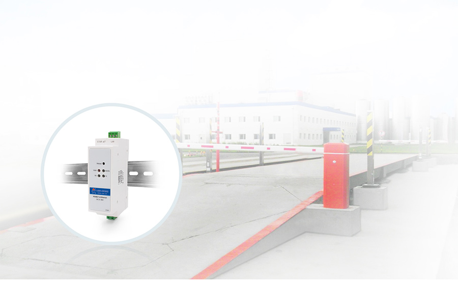
Unattended Weighing
Connect serial to ethernet converter USR-DR302 to barrier gate and it can realize remote control
of barrier gate by Ethernet in control center.
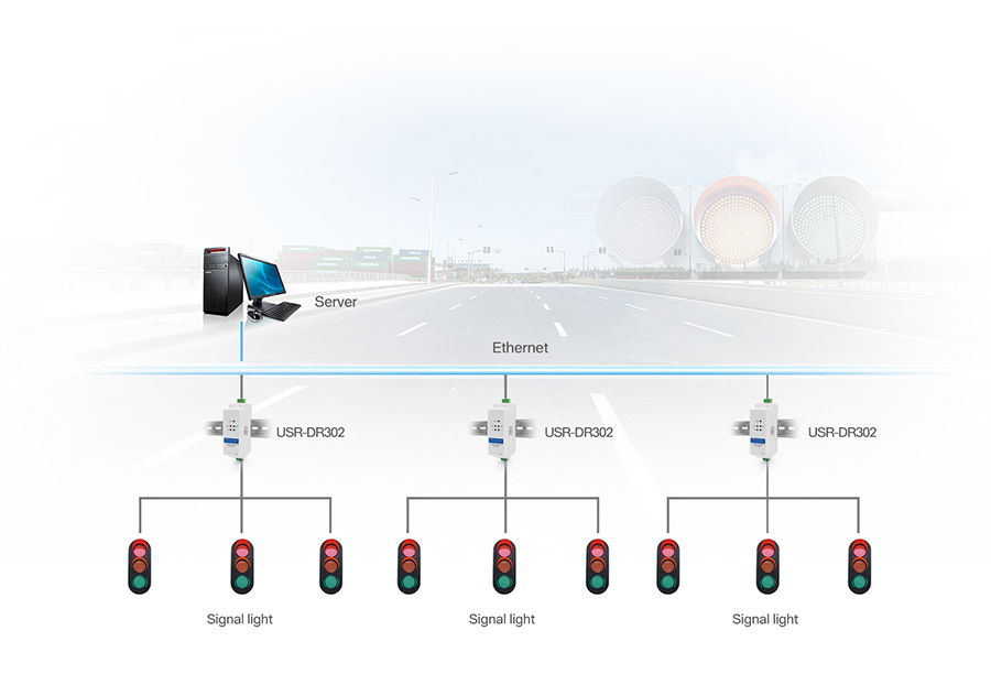
Traffic Lights Management System
Connect serial to Ethernet converter USR-DR302, and it can realize traffic data acquisition and
processing by Ethernet in the control center. And the control room personnel can quickly
make traffic scheduling and planning according to the site condition.
Data Transmission Test for serial to Ethernet converter USR-DR302
Data transmission test for RS485 serial to Ethernet converter is based on the default parameters, please refer to the following steps:
1.Open test software “USR-TCP232-Test.exe”, and do hardware connection according to Chapter 1.1 Hardware Testing Environment
Click https://www.pusr.com/Support/download_hits.html?id=304 to download "USR-TCP232-Test.exe".
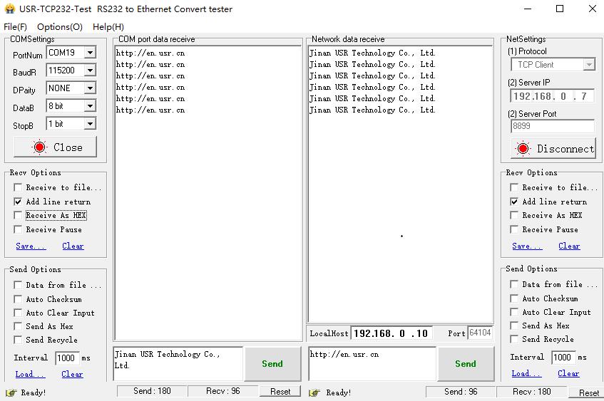
2.The right side is Network Settings: TCP Server, IP address: 192.168.0.201, port number: 8324, click “Connect” to build TCP connection
The left side is Serial Settings: Baud Rate: 115200, Parity/Data bit/Stop bit: None/8/1,
Click “Open” to enable the COM.
Then we can test data transmission between COM and network.
Data from serial to network is: PC’ COM->USR-DR302’ COM->USR-DR302 Ethernet port->PC Network;
Data from network to serial is: PC Network->DR302’ Ethernet port->DR302 COM-> PC’s COM.
The below picture is for your reference:
DR302 Unable to Collect Data When Contact with USR IOT Cloud
Serial to ethernet converter USR-DR302 unable to collect data when contact with USR IOT Cloud
Cloud Link: https://account.usriot.com/#/login
Setting problems:
Unable to find the serial device server USR-DR302: make sure the serial device server DR302 and computer are on the same LAN
Connect to the industrial router and select DHCP.
Registration package: Type is USR cloud, do not write wrong device number and password.
Work mode: TCP Client, IP: tcp.mp.usriot.com , port number: 15000
Click save parameter after setting.
Unit exception:
Check the power supply and confirm whether it is the supporting power supply. If not, replace the supporting power supply.
With the multimeter supply terminal, see if there is voltage, no voltage is the adapter problem.
Only the work light is not on. If other lights are normal, it may be the problem of the light.
Connection problem:
DR302 is 485 interface. RS485 cable is used.
RS 485: A contact to A, B contact to B.
USR IOT Cloud setting problems:
The template selects cloud collection MOBUS RTU
Fill in the correct slave number (equipment number)
The function code and register address corresponds to the real function code of the device.
Terminal device upload instructions should follow the MODBUS RTU format.
DR 302 serial port parameters are consistent with the terminal equipment.
Serial to Ethernet Converters: Cannot Search the Device
Troubleshooting: Serial to Ethernet Converters-Cannot search the device
1. Check the hardware connection:
a. Whether the power supply is normal
b. Check whether the network port lights are normal: The green light is always on and the yellow light is blinking.
c. Whether the module is directly connected to the computer through a network cable. If so, it is recommended that set the computer to the following parameters:
IP: 192.168.0.201.
Mask: 255.255.255.0
d. If not, ensure that the device and computer are in the same network segment. Check if they can ping each other.
2. Check if the computer status is normal:
a. Check if anti-virus software and firewall are turned off.
(Some anti-virus software and firewalls will block unfamiliar ports, anti-virus software will report viruses to unused software)
b. Whether the computer has dual network cards.
(Please turn off other network cards during the test.)
How to send AT command?
1.What is the AT command?
AT command is used for controlling module. You can use AT command to configure and query the settings.
2.How to use the AT command?
For USR device is in transparent mode normally, you must enter AT command mode at first. Then you can send AT command to configure or query the settings. After you configure the USR device, you should restart the USR device to make the settings take effect. Every time module restart will work in work mode rather AT command mode. Every AT command must add character carriage return and line feed . In Hex, is 0x0D is 0x0A.
Powered successfully, we can setting the module with UART.
The default UART port parameters of the module are: baud rate1152000, no parity, data 8 and stop 1.
Recommend to use secureCRT software tool or testing program of USRIOT.
Below are using the secureCRT to operate AT command:
Need two step as below:
Fill “+++”in the UART. After the module receive the “++++”,then will return an “a” to confirm;
When you receive an 'a' , then you need to send other 'a' within 3 seconds
After that, module will return “+ok” to enter into the commend mode.
Fill “+++”and “a” need to achieve in the time to reduce the chance of entering command mode while working normally
accidentally. Detail requirement are as fellows.

Time requirement:
T1>the interval of serial port package
T2<300ms
T3<300ms
T5<3s
Change transparent transmission mode to AT command mode :
1. Serial mode device send “+++”to module continuously. If the module received ‘+++’ successfully then it will send “a” back.
2. When module received “a” and then user need to send other “a” to uart within 3s.
3. The module will return ‘+ok’ when module received ‘a’ successfully. And enter into command mode Change AT command mode to transparent transmission mode:
1. Serial device send “AT+ENTM”to module.
2. After the module receive the commend, feedback “+ok”, then back to the previous working mode.
Example: Use USR-TCP232-Test.exe software to send serial command or use your own serial software or MCU send command to our module.
Open test program and configure the serial parameters. Click ‘Open’:
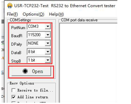
Send +++ to serial. Notes do not add a SPACE or ENTER, that will not return the correct character.

If you give a correct command, the module will return an 'a' likes this:

When you receive an 'a' , then you need to send an 'a' within 3 seconds. You can not add any SPACE or ENTER either.

The module will return +Ok. The the module enter into the AT command mode.

Now you can send AT command to the module, but you should add an ENTER after your command.

3. Network AT Command
Ensure that the module and the computer are in the same network segment before enter into the mode of network AT command. Send www.usr.cn to port 48899 via UDP broadcast of ethernet port. If the module and the PC are in the same network segment, the module will receive the answers. Then it indicates that the modules has entered into the mode of network AT command, and the parameters can be set by AT command. But the module will automatically exit the network AT command mode if there is no command within 30s under AT command mode.


